Design Guide
Design guide is some suggestions for designing membrane switch from Sun Rising, as a manufacture, which includes key information needed for manufacture; attentions when designing graphic overlay and circuitry; Mechanical Restrictions for thickness, LCD windows, keys, tail, and LEDs; connector’s type fit for membrane switch’s tail; attentions when installing membrane switch on holding panel. abiding above suggestions will make producing easier, save cost and increase quality reliability.
Key information needed for manufacture:
Right is an example showing key information such as graphic overlay’s size, colors and metal or poly domes; tail’s output position and length and space among lines on tail, circuitry’s shematic:
Attentions for designing Graphic overlay
Dimensional drawing such as CorelDraw, Adobe Illustrator or CAD document with all texts to be curved is accepted by our machine. If there is no size file, actual sample is also acceptable. we will make art work based on actual sample for your confirmation.
Color matching: Pantone or RAL. Attention: please offer us Pantone color U for sand surface such as Autotex F/ V, Autotex EX F/ V, Autoflex EBA or Laxan 8B35, Pantone C is for glossy surface such as Laxan 8010, Autoflex EGB
Printing type size and line thickness: text, logo or icon’s minimum type size is 2 mm*2 mm; minimum line’s thickness is 0.2 mm.
Closed frame line with less than 4mm from the outer edge off the membrane is prohibited as Printing tooling has position error of 0.2 mm so closed frame line is difficult to be centered, but interrupted line can avoid the error and is permitted, as we can print interrupted lines separately.
Attentions for designing Circuit
Customer can just send us schematic, let us make workable circuit layout for your confirmation.
Tail cannot be under key.
For water proof membrane switch, if possible, try to make tail be toward membrane’s center and within membrane frame, then, no extra gasket is requested and additional cost is saved.
Embossing
Key’s embossing includes: Pillow embossing, Dome embossing, Rim embossing and Two-tired embossing, , which function is to assist finger location.
- Keys can be embossed in various shapes— round, oval, square based on the face plateBraille designed by customers
- Braille like “small hill” on the overlay, through which blind people can read.
- LED window, dome embossed for holding the LED inside.
Embossed height is less than 100% of the film thickness. Minimum internal radius at embossed corner is 0.5 mm.
Mechanical Restrictions
There are certain mechanical restrictions within a membrane switch panel, we highlight the most important:
Holding panel should be 0.1 mm to 0.2 mm deeper than the membrane switch’s thickness (normal thickness for membrane switch is 0.85 mm-1.0 mm). Sometimes, overlay is much low in holding panel, we can increase overlay’s total thickness by adding several sheets.
LCD Windows:
Edges of windows should be a minimum of 3.00mm from edge of membrane switch panel.
Edges of windows should be a minimum of 4.00mm from edge of switch positions.
Edges of windows should be a minimum of 9.00mm from centre of SMT LED’s.
Embossed Switches (Keys):
Edge of switches should be a minimum of 5.00mm from the outer edge off the membrane or from edge of other switch.
Edge of switches should be a minimum of 2.00mm from outer edge of SMT LED area.
Tail:
Output position from reverse side should be a minimum of 3.00mm from edge of the membrane.
LED’s:
Centre of SMT LED’s should be a minimum of 8mm from edge of the membrane.
Connector Tail
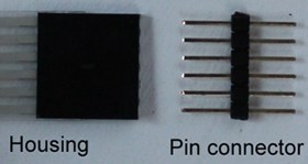
There are 3 kinds of connector which is used for common (silver er circuitry) membrane switch’s tail.
- Housing and pin connector for 2.54 mm centers.

- Solder connector directly to PCB usually for 2.54 mm centers.
- Non-ZIF connector used for 1.0/1.25/2.54 mm centers tail.
- ZIF connector with slip clock is prohibited for silver circuitry tail, which will damage silver circuitry. That can only be used for FPC tail.
Attentions for Installing instruction:
- peel off the protective glue paper in the tail area.
- Pass the tail through a cut-out in the holding panel
- Ensure keypad is aligned on backer plate properly.
- Progressively peel the protective glue paper off, moderately bend the membrane switch, slowly glue it on holding panel and lightly press it by a rolling panel.
- Test all button domes after adhering to backer plate
Special Reminding:
- membrane switch should be installed in the flat position.
- Do not bend Excessively (bending degree of not more than 15 degree) membrane switch when mounting.
- dirt and air must not stay trapped under the membrane switch
- If keypad is misaligned on backer plate, remove and discard keypad. Do not reuse keypad if removed after application.
- If keypad is removed from backer plate, ensure that all adhesive residue is removed from backer plate before installing new keypad.


